JB Tuning
Initially, I was hoping to do most of the work myself but soon realised that a lot of it would required a specialist, especially as I wanted it customised.
I contacted John Balcomb of JB Tuning and he agreed to take on the project. I gave John my list of requirements as follows:
• Blast the bodywork back to bare metal then prime and re-spay in black.
• Install a new wiring loom and control cables.
• Fit a 250cc race tuned engine with a five-speed gearbox and racing clutch.
• Add a 30mm carburettor with racing exhaust.
• Uprate the front and rear suspension.
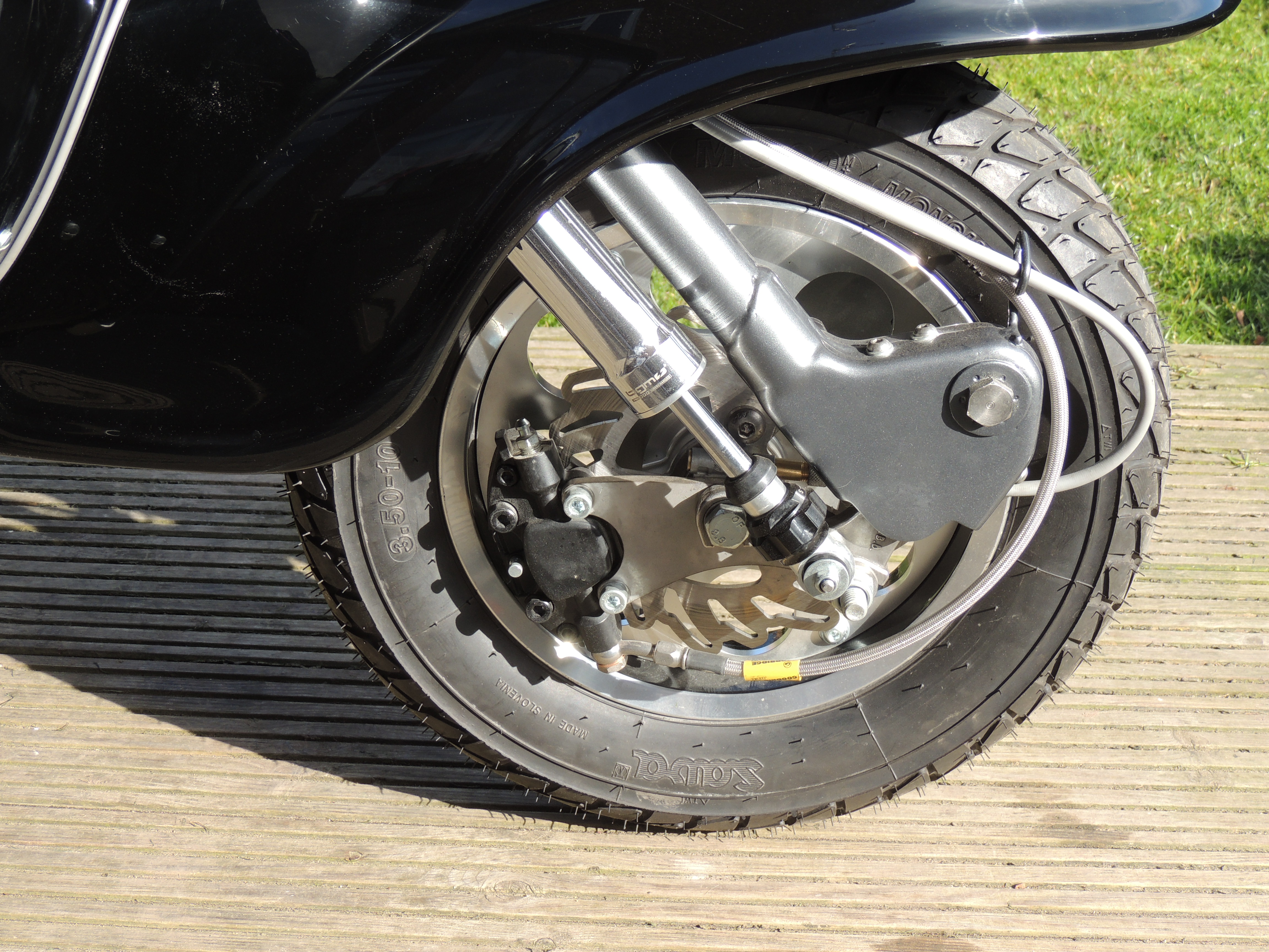
• Fit servo assisted front disc brake.
• Use SIP wheels with tubeless racing tyres.
• Fit SIP digital speedo/rev counter.
• Add Electronic ignition with 12volts DC electric.
• Change the rear lamp for an LED one.
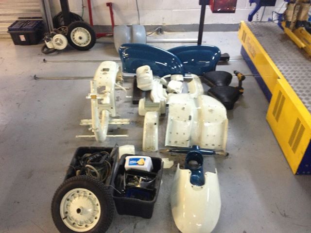
The photo below was taken after dismantling.
Background to Project
In 1964 I bought a second-hand Vespa GS150 four years after falling in love with a picture of one I had seen in an Ian Allen book. I didn’t want to own a Lambretta not even the latest TV200. However, one evening in 1965 I went for a drink with some friends in the Shakespeare pub, Goswell Road and met a lad who owned a TV175 Series I Lambretta, which had been painted black. It looked classy and left a lasting impression.
Fast-forward to 2013 and my love of Italian scooters had been rekindled. I already owned a 1960 Vespa GS150, which had been fully restored and I was looking for a new project.
I remembered how I had always loved the Series I TV175 all in black and decided to make that the next project. As Series I TV175s are very rare and expensive, I set about finding a Series I Li. As I wanted to customise the scooter, an Li was the best bet as it would be sacrilege to customise a Series I TV.
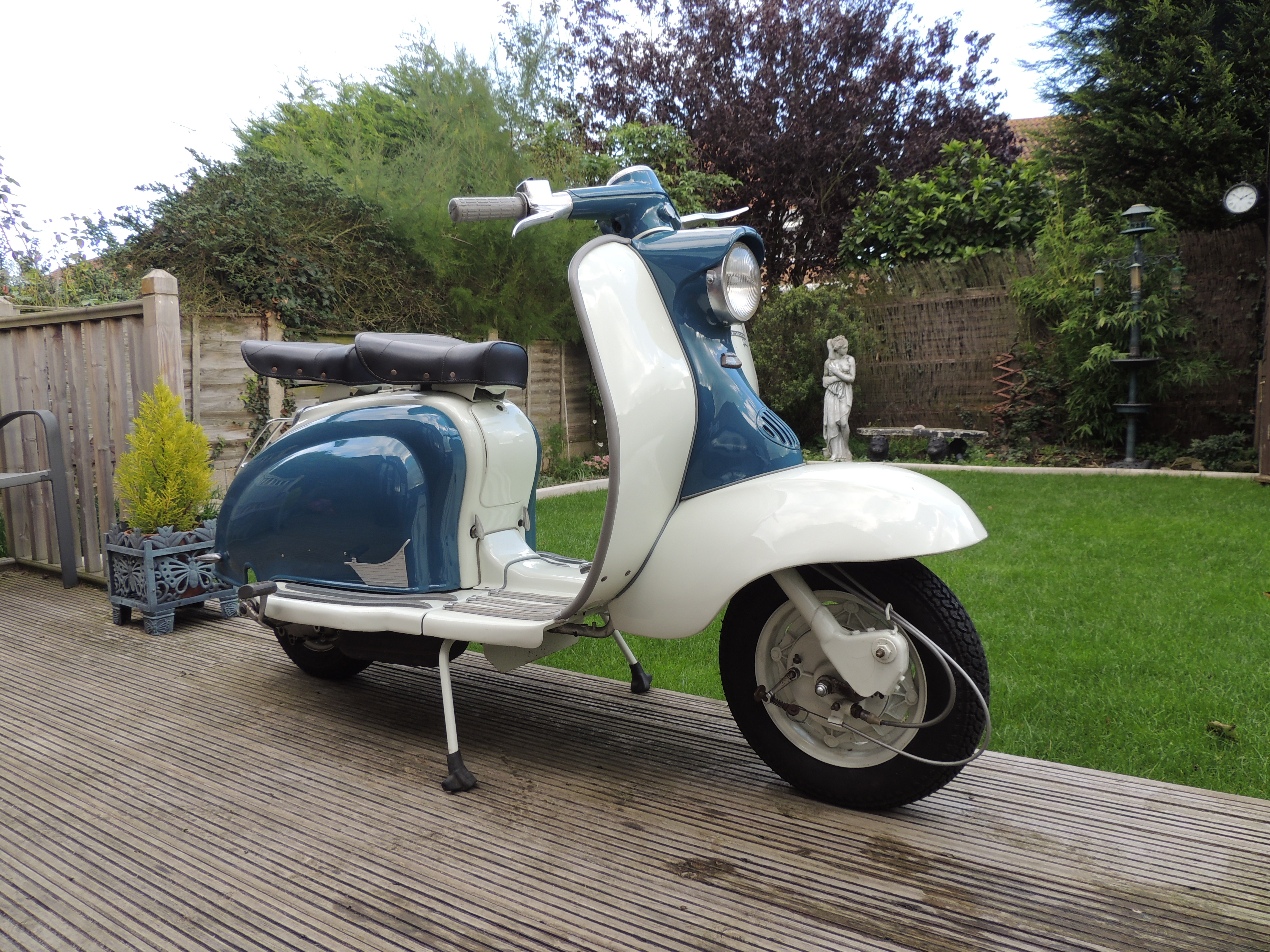
I managed to buy an Li150 for £2500. It had been crudely restored to its original blue and light blue, typical of the late 1950s. Please see photo below.
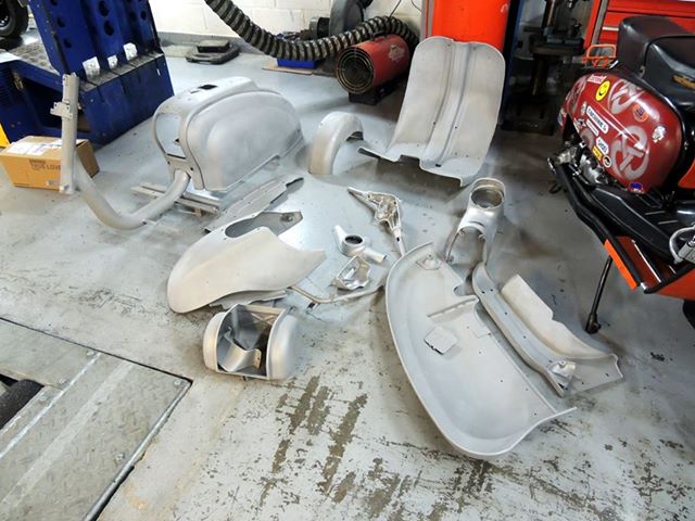
The picture below shows all the body parts after they have been blasted back to bare metal. Most of the bodywork was rust free, which is unbelievable for something so old and Italian! I can remember the wings on my 1964 mini rusting badly in 1967! Unfortunately, the leg shield was rusted beyond repair and finding a replacement proved difficult. In the end we had to use a remade one, which was difficult to fit and required some modification.
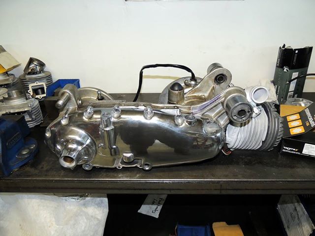
Below is the 256cc engine that JB Tuning built for me. It has a racing clutch with 5 speed gearbox. Once coupled with a 30mm carb and racing exhaust it was dyno tested and produced 27.5bhp, over 4 times more powerful than the original 150cc engine.
Project Problems.
As with all project there were some problems as follows:
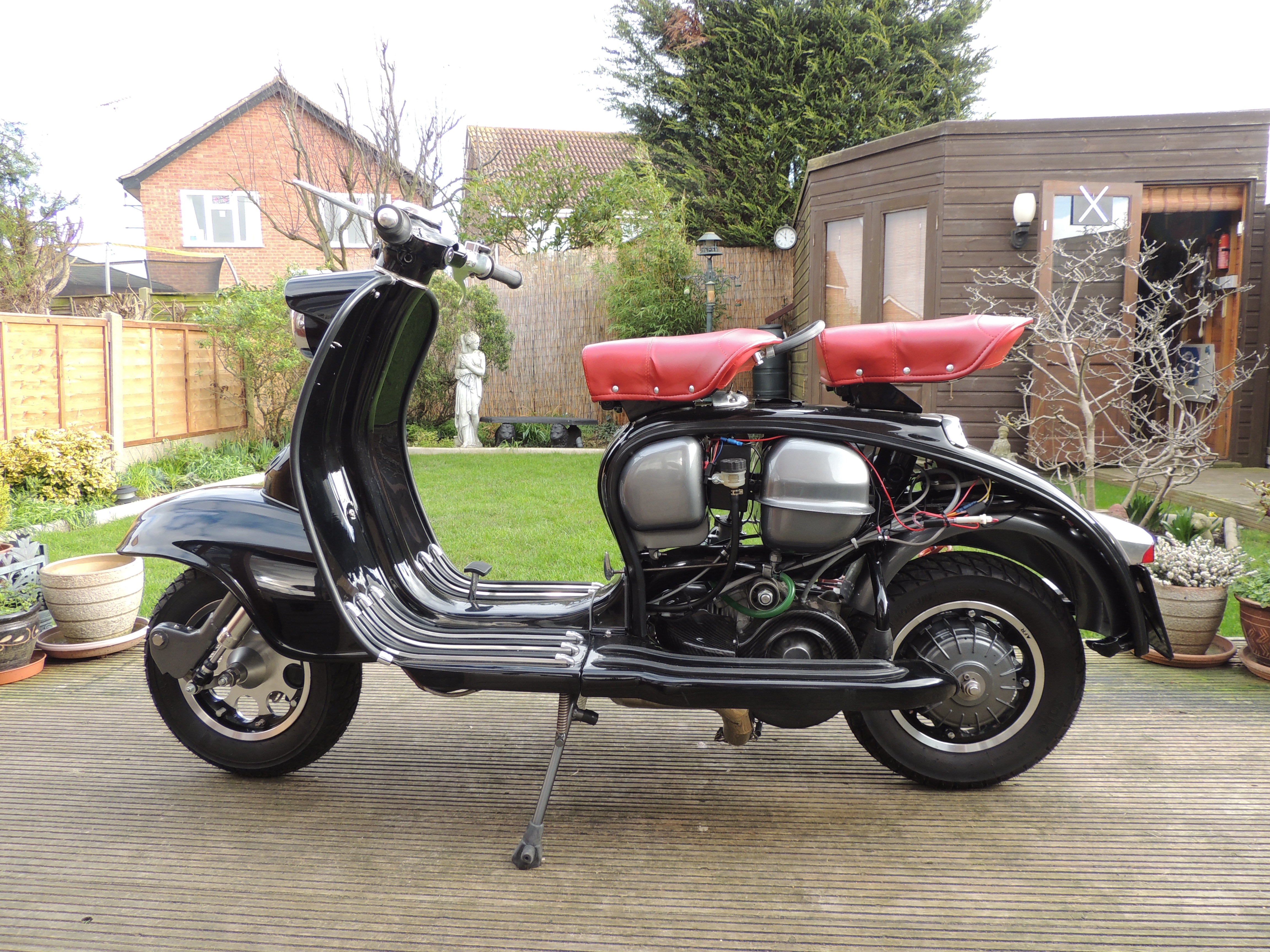
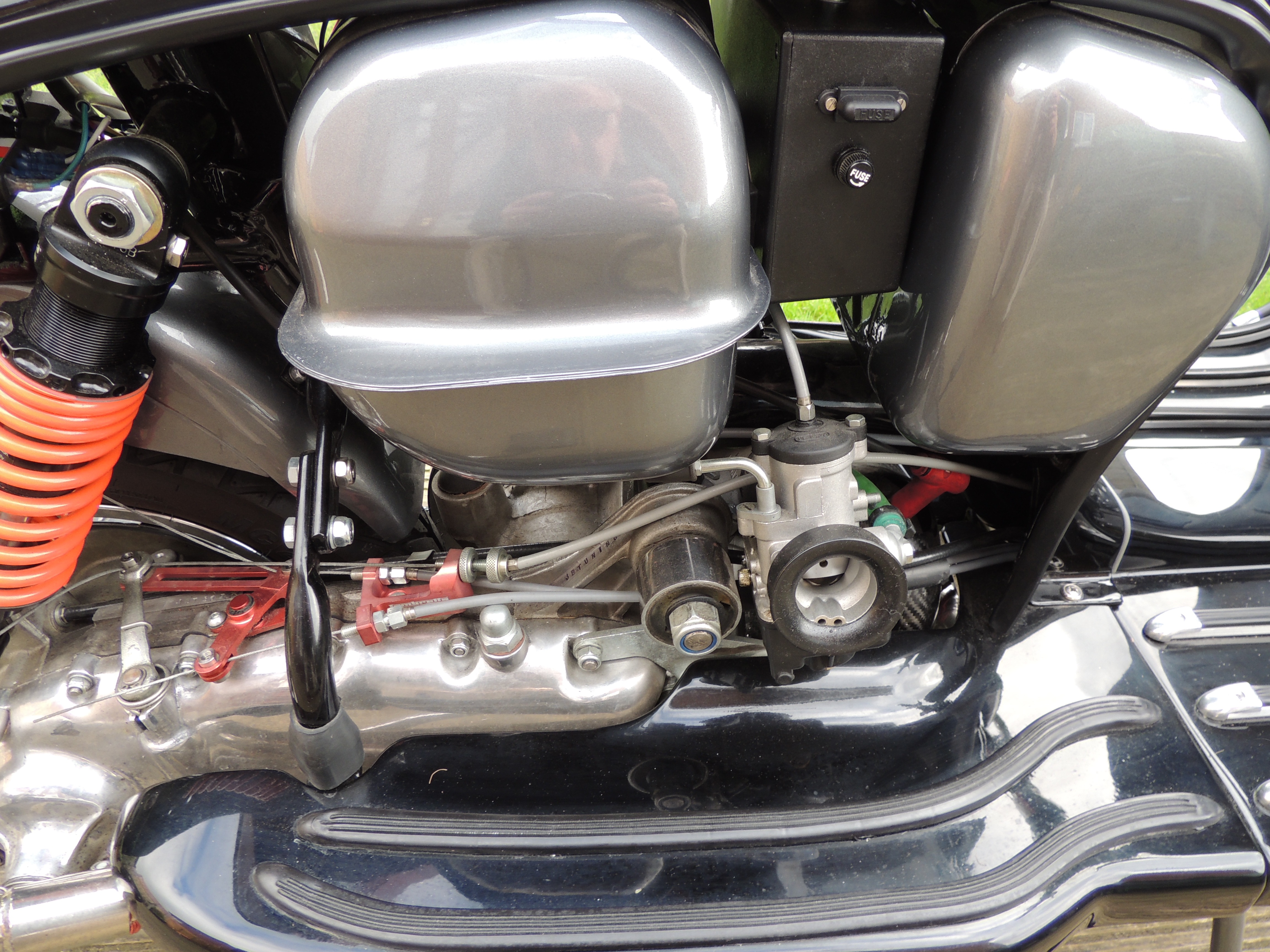
Battery.
JB Tuning had to remove the battery tray to make room for the Dellorto carburettor and the throttle cable. Unfortunately, I needed a battery to feed the tracker and I needed 12volts DC for the LED bulbs. What’s more, the Wassell voltage regulator and BGM PRO DC stator need a battery in the circuit to work.
I noticed enough room between the toolbox and the fuel tank to mount a battery mid way up but no obvious way to secure it. I worked out that I could mount a plastic battery box in the void by hanging it from the air intake bolts under the front seat.
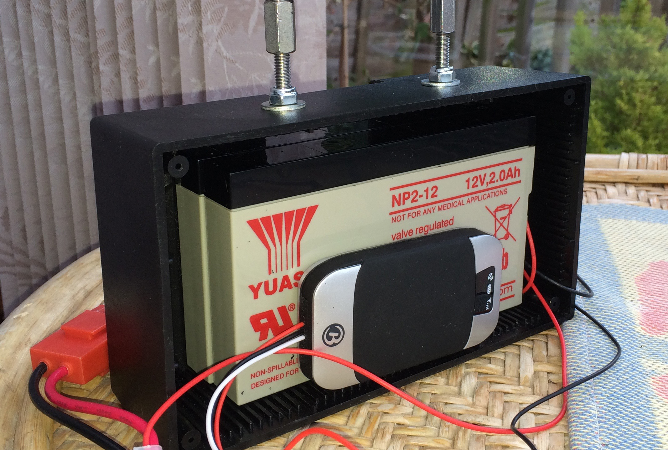
Initially, I made a lithium battery to fit in the box out of 12 Samsung 18650 batteries together with PCBs protecting each cell from overcharging. However, I chickened out of using it when I realised that lithium batteries had a habit of exploding especially as it was right next to the fuel tank! So I looked for sealed lead acid batteries instead. Unfortunately, I couldn’t find a single battery of 12volts and at least 4Ahr capacity to fit in the space available in the box so I had to settle of two Yuasa NP2-12 batteries connected in parallel to give 4Ahr.
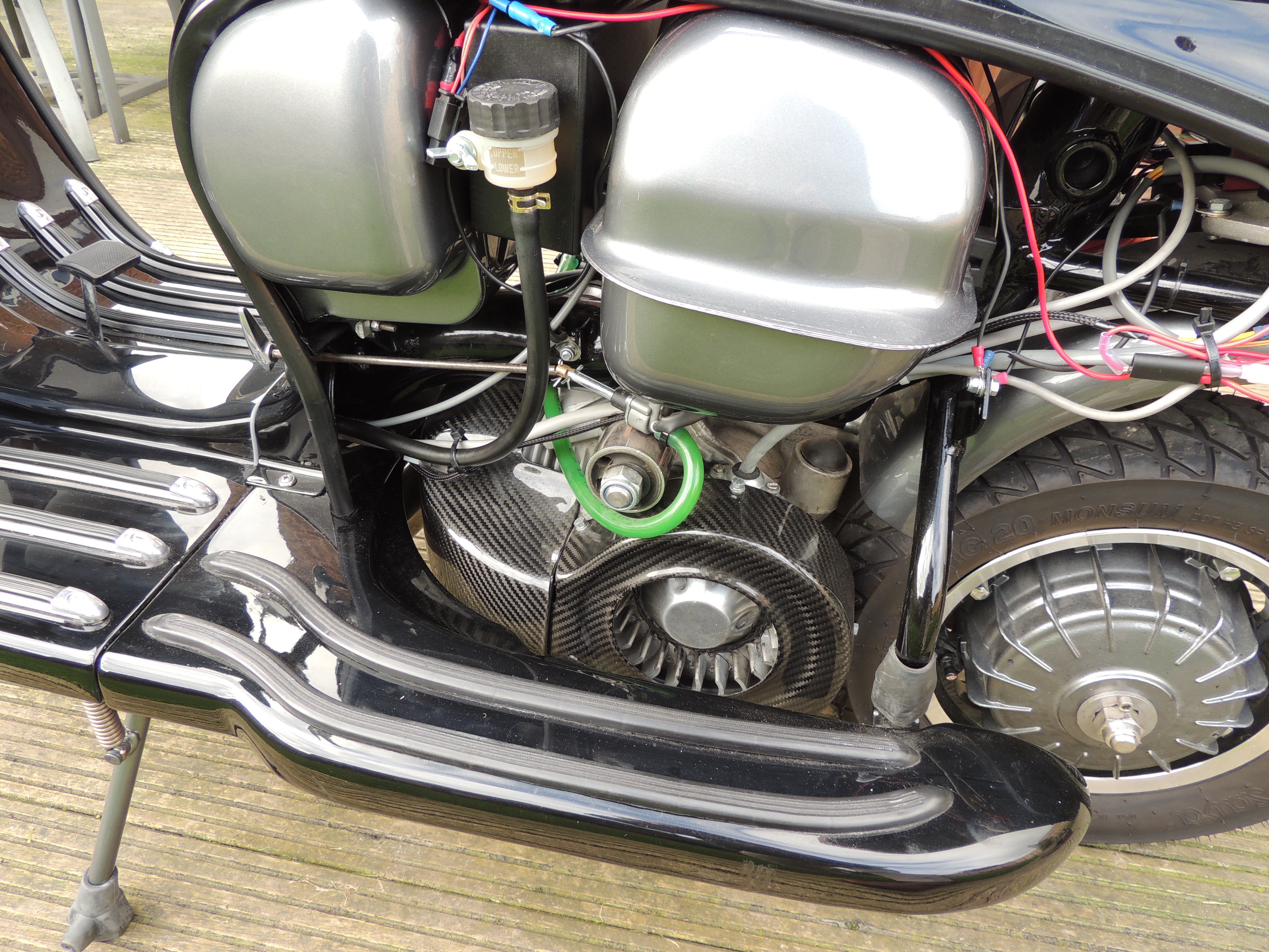
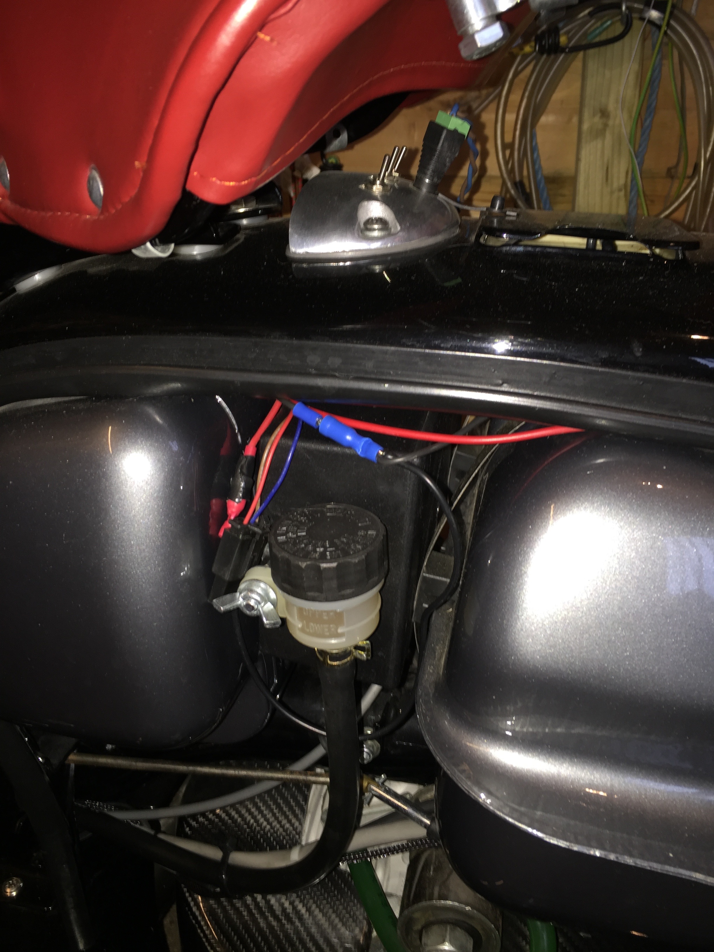
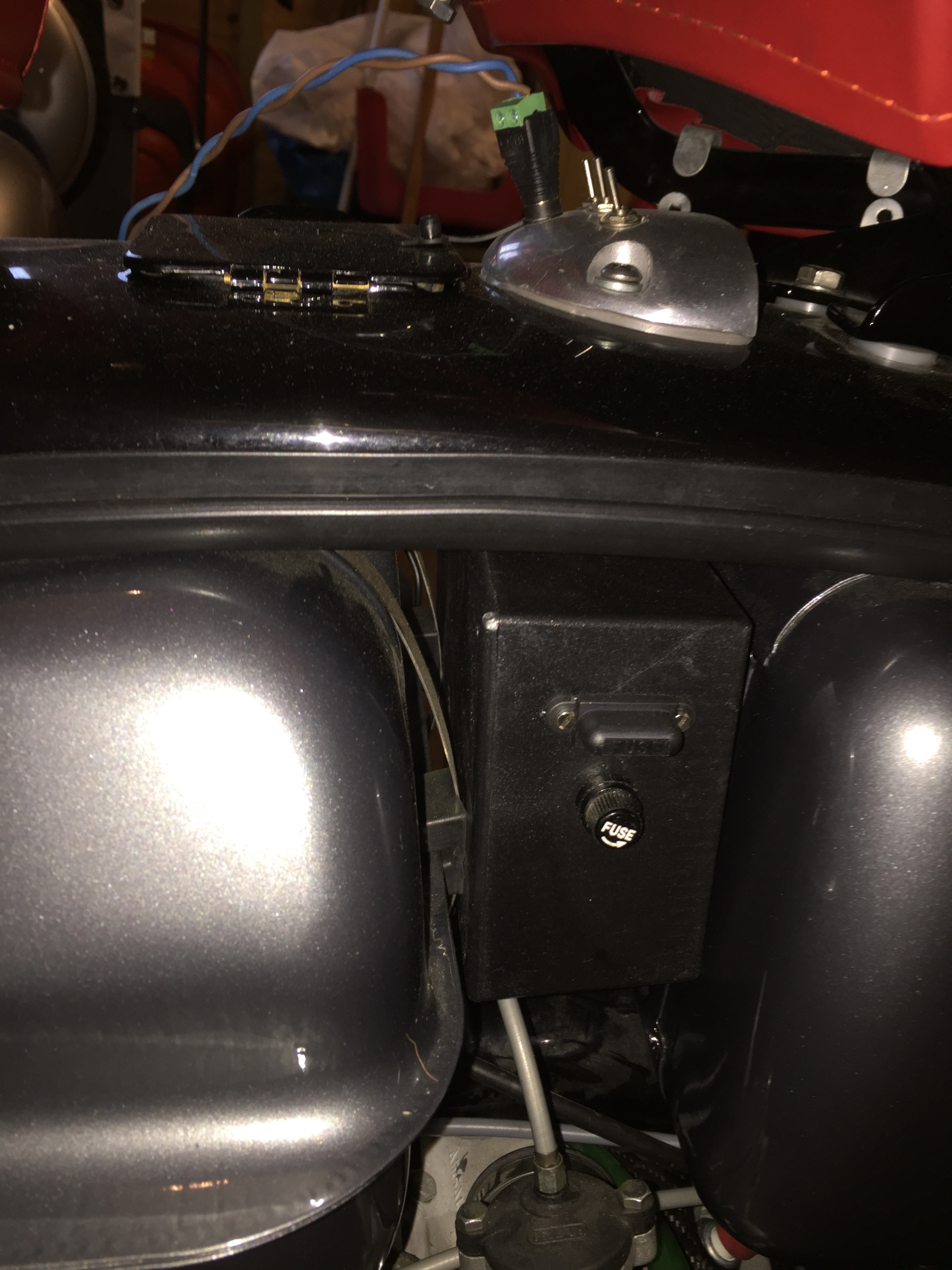
The photo below shows the nearside view of the installed battery box, which hangs from the air intake. Fitted to the air intake are three spot lamp switches and a charging socket. The switches are miniature 2amp ones, which are more than capable of handling the current generated by the LED bulbs I’ve installed in the spot lamps.
Mounted on this side of the battery box is the servo reservoir for the front hydraulic disc brake.
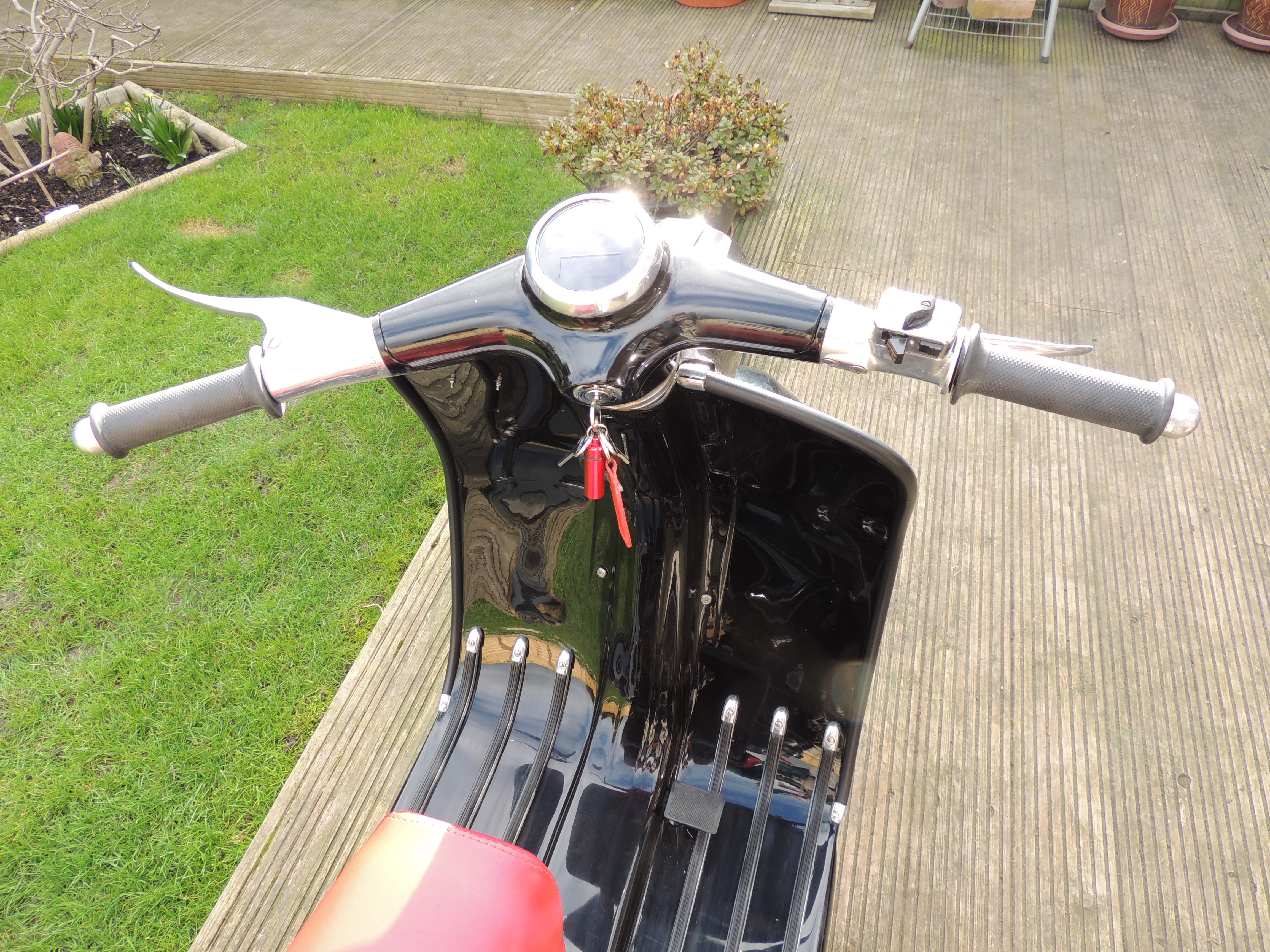
S.I.P Digital Speedo
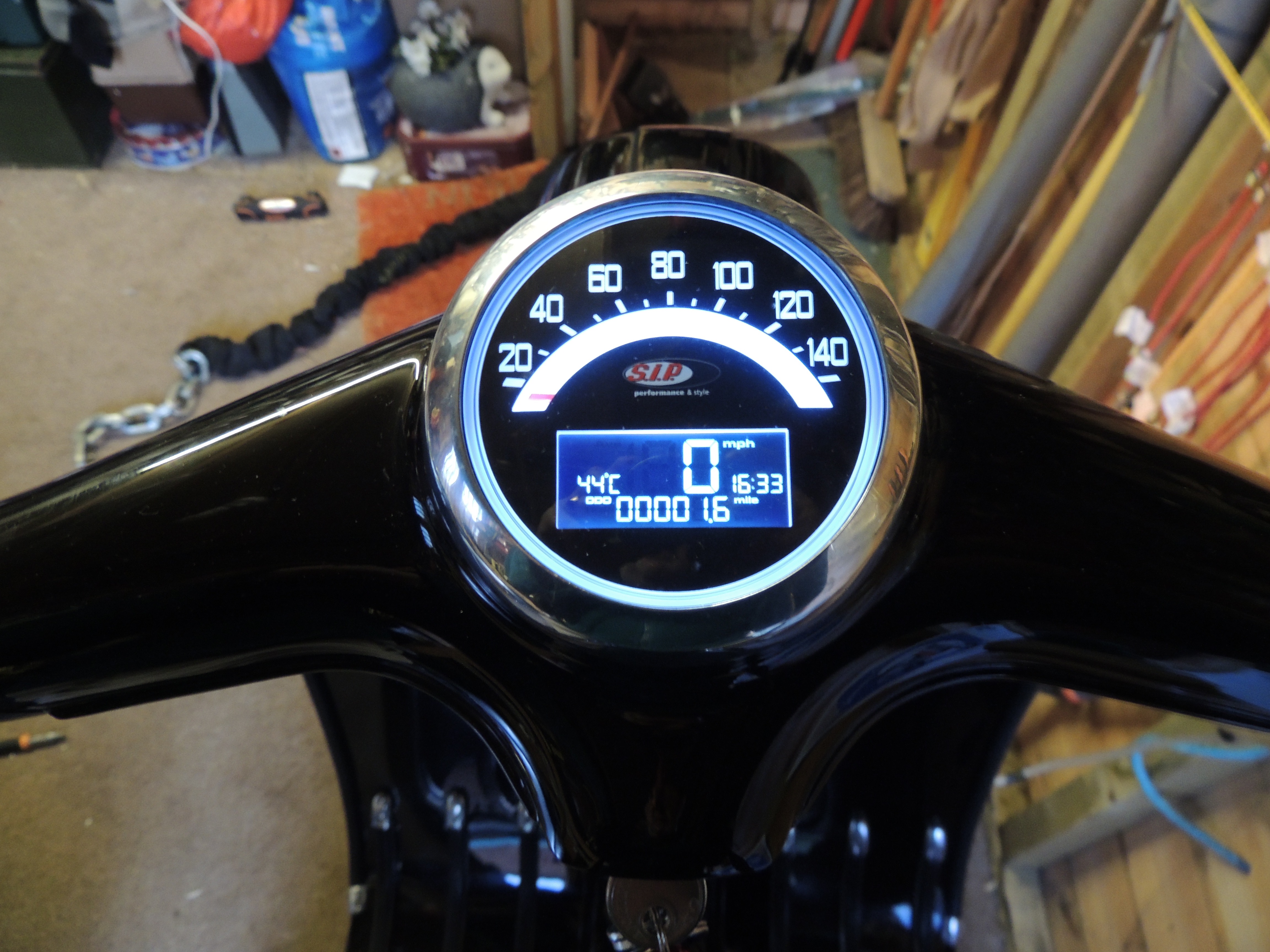
The SIP digital speedo wouldn’t work when connect to the DC lighting circuit even though SIP said it should. I looked for a solution on the Internet and found an explanation on why it wouldn’t work and a fix. The Wassell regulator produces a pure DC voltage and the SIP speedo needs to detect pulses caused by the engine to work. The solution was to run a lead connected to the unregulated AC output from the BGM stator. I was a bit worried that, as the voltage could be up to 30volts it might damage the SIP speedo but the SIP power box seems to handle it okay and the speedo works fine.
The photo below shows the speedo.
The following diagram shows the AC circuit that feeds the S.I.P. digital speedo.
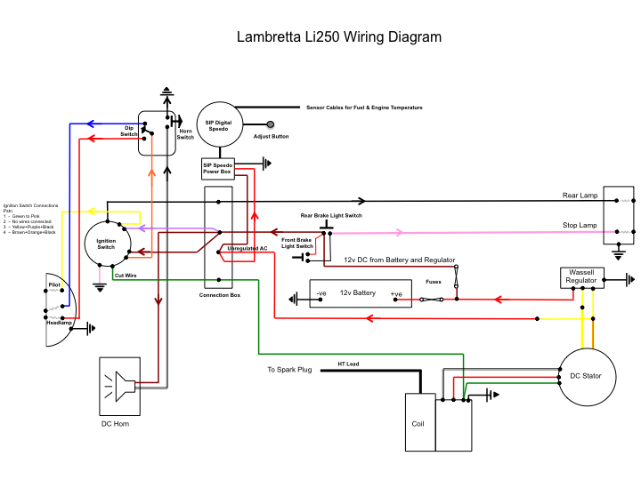
Wiring
Due to my insistence of using a DC stator, Wassell regulator, LED lighting and a SIP Speedo, the wiring was giving JB Tuning a headache. This was compounded by the use of an ignition switch, which wasn’t totally compatible with the original cut switch circuit and the Li lighting switch. This gave me the opportunity of working out how to do it and once I was sure, producing a bespoke circuit diagram. I had to order some additional wiring, connectors and fuse holders but once they had arrived, I made the changes and got it right first go. Not something that happens often for me.
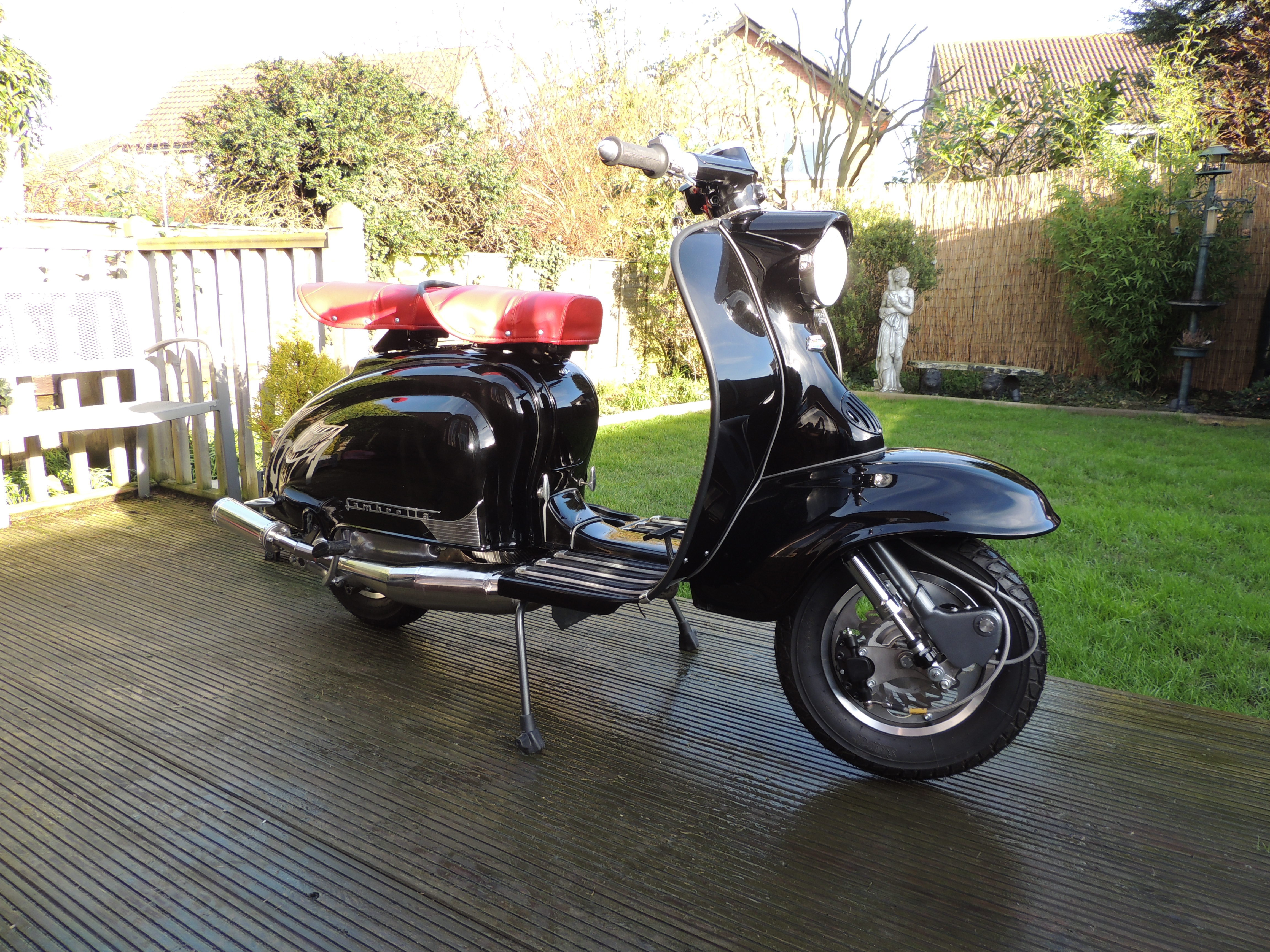
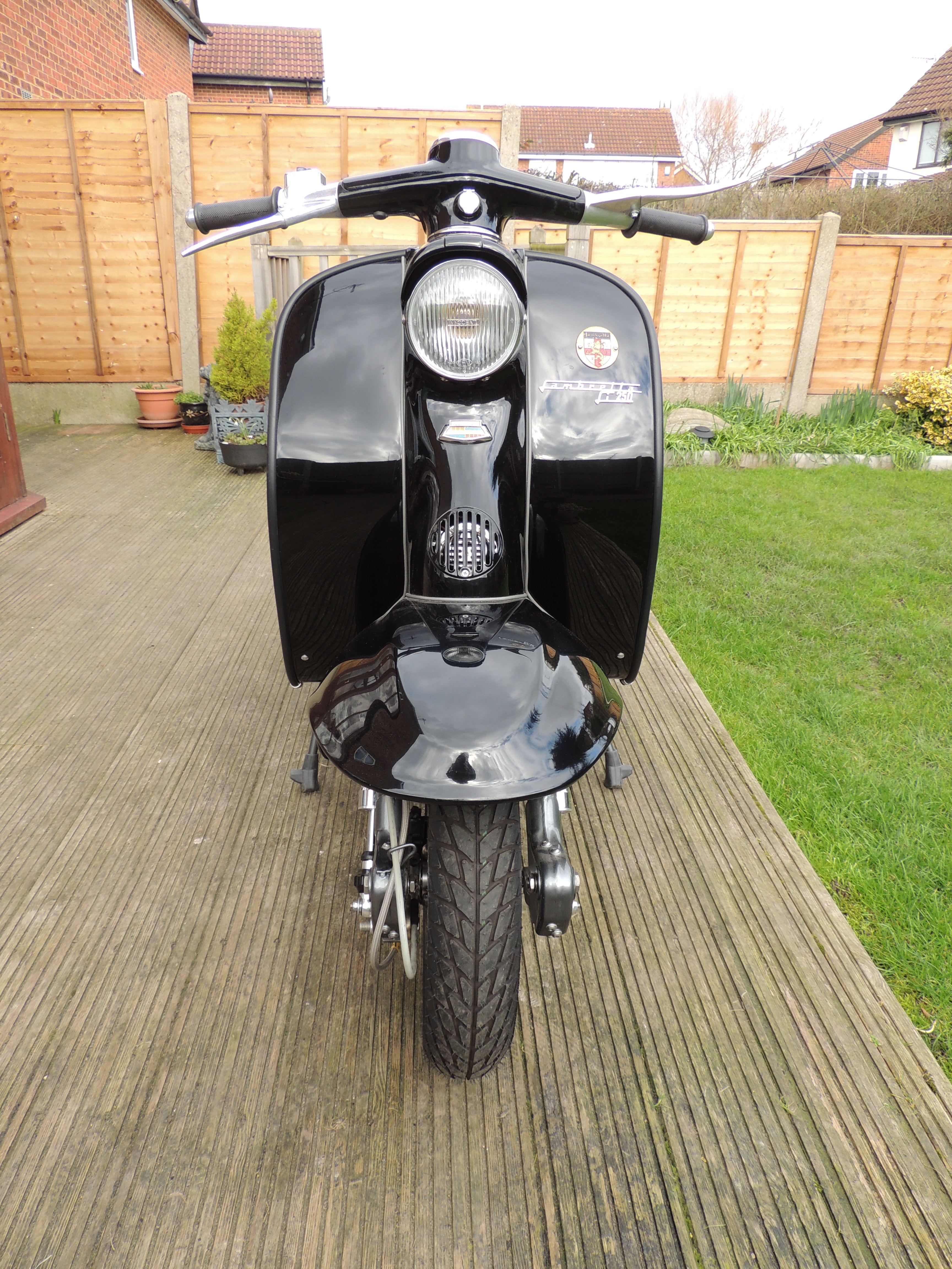
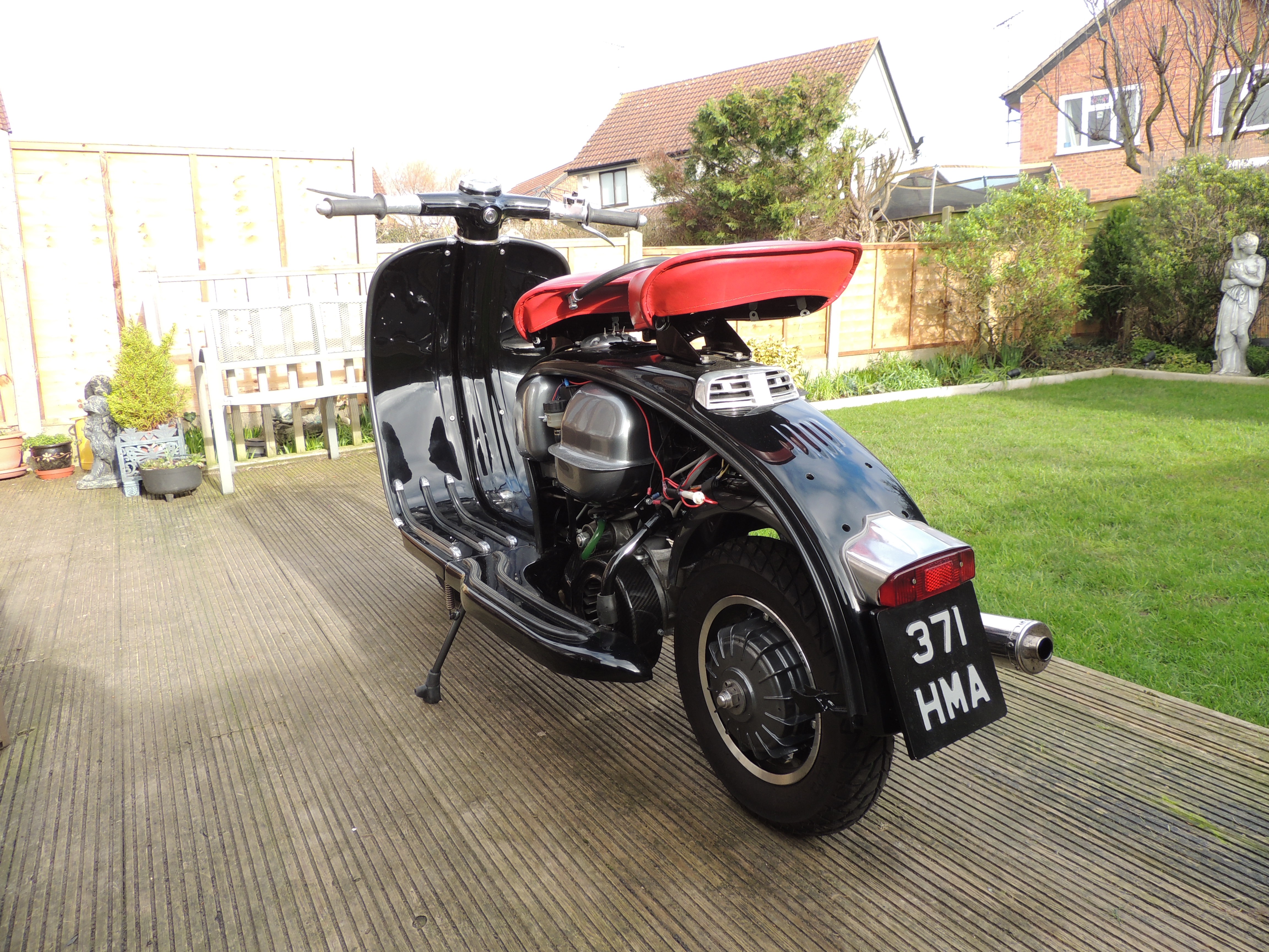
Completed Li250
The following photos show my Li250.